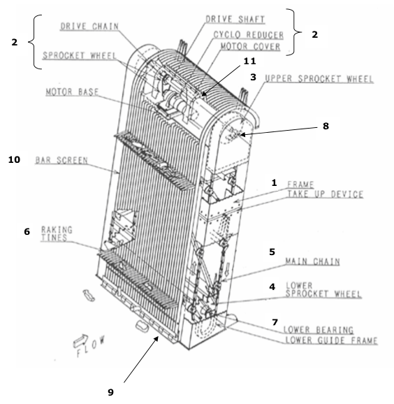
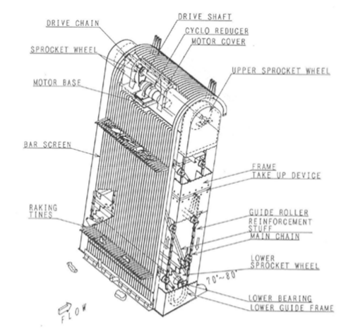
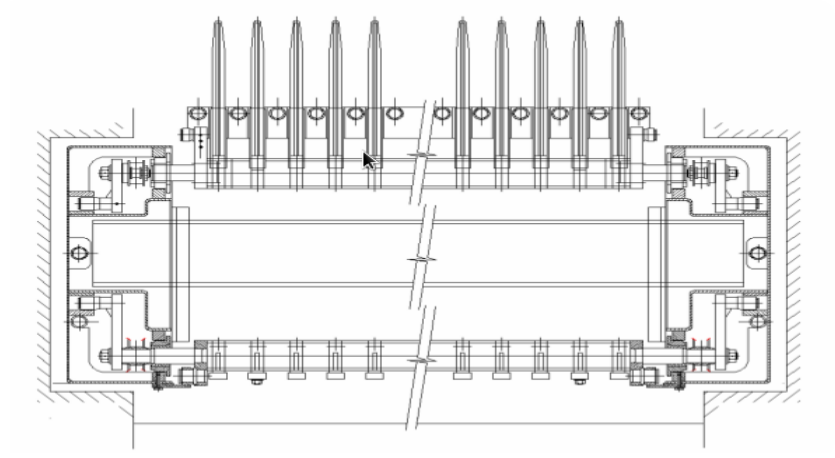
Frame (1 on the left and 1 on the right side) in 2 pieces. Both parts have a movable part to tension the main chain
2
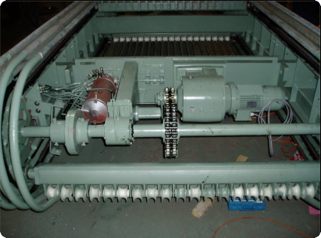
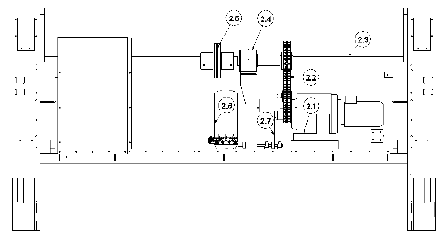
Drive mechanism (see drawing on page 5 + drawing on page 6) is made of:
2.1
motor: brake motor Renold AMP 120/3 - 3 kW
2.2
drive chain between motor and main shaft - 11⁄4 Duplex
2.3
main shaft in 2 parts
2.4
intermediate bearing
2.5
coupling
2.6
automatic lubricating pump Woerner PMF-C-10/12,7 – 10 l
2.7
chain transmission to the lubricating pump type 06B1
3
Upper sprocket wheels type Renold 12T/6”
4
Lower sprocket wheels type Renold 12T/6”
5
Main chain type 6” galvanised
6
Tine beam with fingers
7
Lower bearing
8
Upper bearing
9
Support basis
10
Bars
11
Protection hoods
Screen operation
A
The raking tines insert into the weed or debris mass at the base of the
intake channel on the upstream side of the screen. The tines move upwards
from the base of the channel.
B
All working parts are protected behind the static screen and consequently
function on the clean side of the bar screen.
C
The raking tines move upward through the bar screen forming an angle of 90°
to the bars. At the top of the screen the raking tines describe an arc until
they are almost vertical.
The tines start the retract cycle on reaching the top of the travel, thus
cleaning the tines and enabling all recovered waste to drop by free fall to a
conveyor belt or a waste container.
After cleaning, the tines start the descending motion through the curved
section of bars at the top of the unit. No obstruction is possible between
the recovered waste and the tines, because the tines retract within the
downstream side of the screen frame.
No recovered waste can drop behind the screen, because the screens
are positioned directly against the concrete working floor. There is no
gap or opening between the screen and the working floor.
Neither can any waste drop on the working floor because all
equipment, i.e. the conveyor belt or waste-container, is positioned directly
against the screen.
D
Once arriving at the bottom of the screen, the raking tines return gradually
to their unfolded position, of 90° in relation to the static bar screen, by
turning counter-clockwise.
E
All machines have a bar section of ø 42 mm, a spacing between bars of
50 mm or more and a raking tine length of 600 mm protruding in front of the
screen bars.
Screens with bar spacing of 16 to 30 mm are also available. These fine
screens are used in sewage pump stations. They are equipped with flat bars
of 65 by 10 mm, instead of round bars.
The above deck level portion of the screen can range in height from 1,6 m to
2,4 m. The height of the curved section above deck level varies depending on
the method of discharge, i.e. onto a conveyor or into a container.
F
All screens are “Tailor-Made” and manufactured in mild steel or in
stainless steel grades 304 or 316, in widths ranging from ± 1,5 m to ±
4,5 m and ± 2,5 m to ± 18 m high.
The screens are manufactured to the requirements of the customer;
quotations are calculated taking into account screen dimensions and materials
of construction.
G
Check on overload: in case of overloading (when load is more than
2000 kg): the screen will stop automatically by cos φ controller. The screen
will operate again after removing the excess load (or blockage).
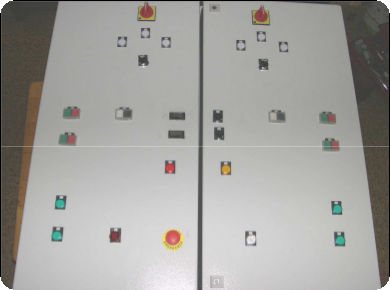
Control cabinet
When needed and on simple demand MOTOGROUP can also deliver the control
cabinet.